
After completing a project which I had to design a custom railing for a stair, I decided to share my experiences with you. Although the project was done in Revit, however , I investigated how I could achieve the same result in ArchiCAD 16. See the picture .

Before we jump into the software, I want to remind you of some things you need to keep in mind. As I have mentioned in my previous post, "BIM is not just a MODEL, its a DATABASE"
- Know the intent of your model, ask yourself why do you need to model the object? what impact does it have on the overall design?
- If it worth modelling, what will be the level of detail (LOD) throughout the design development stage?
- there is always two or more different methods to achieve your results, if time permits, investigate different methods and choose the one that best suits your intents or office workflow. Consider efficiency and Time.
- Understand your deliverable.
Lets get started!
here is what we are going to create
 |
| Revit Railing |
 |
| ArchiCAD Railing |
Lets start with Custom railing in ArchiCAD16.
Custom Railing can be achieved using different methods and tools in ArchiCAD, for this tutorials I used the morph tool in ArchiCAD 16 because I think it is the best option in this case. Therefore you need AC16 to follow this tutorial.
You can customised your railing using other tools like;
Wall, Slab, Mesh, Column, Beam , Complex Profile and Shell tool in AC15. Depending on what type of railing you are creating, using some of the these tools, you might face the challenges of rotating the object to the right position and saving your railing to the proper object library in order to schedule them properly.
Step 1
Modelling the Balusters
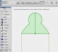
- Use a reference image, Here is the baluster profile image I found online and I decided to use Number 3.

- Import the image into the worksheets and activate the worksheet in any elevation view then scale it down to the desired baluster height. I divided the baluster profile into 3. Top part is squared, Middle part is round and the bottom part is squared.

- Switch back to elevation view and start the Morph tool. in the info box at the top, choose " Geometry method: box" . Start tracing the top part of the baluster with the morph tool, These are my values; x =100, y= 100 and z = 100.

- For the middle part, change the geometry from box to Revolve and trace half of the profile. Pull your mouse from top to bottom and leave the axis line at angle 90 the click. A box will appear

- Type 360 for the revolve angle and OK.
- The bottom is also a square, so repeat what we did for the top part.
- Check your Baluster in 3D , you should have something similar to the picture below. You can change the material to some wood material.

Select the baluster ( all the parts) go to File- Libraries and objects- Save selection as - Object

STEP 2
The Handrail
Go back to the Elevation view, activate the Morph tool and draw the Railing profile on top of the baluster. you can also draw the profile in section view.
Draw
a line with the morph tool along the path that you want the railing to
follow , then use the tube to push the railing profile along the line.

 |
| Push Along Path |
 |
| End Result |
Custom railing in Revit Architecture 2013.
For this tutorial, we are going beyond the Project environment into the Family editor.
Here is the workflow:
- Draw the Balusters and the Handrail profiles in the family environment using the right template
- Load the profiles into the railing tool in the project evironment
- Edit the railing settings to get what you want.
- Every horizontal members are called RAILING
- The uppermost horizontal rail is the HANDRAIL which can be edited separately.
- Every Vertical members are called BALUSTER
- Baluster Posts, are the END and CORNER Balusters
Steps Baluster
- We are going to choose a template from Revit family. On the start up screen ; go to Families and click New.
- Select template "Metric Baluster Post"
- Open the Left Elevation then go to Insert - Image , import the reference image.
- Scale down the image by dragging the handles as shown in the picture below.
- Draw 2 additional vertical reference planes to both sides of the existing one and dimension them equally.
- Go to "Create- Extrusion. Set the "work plane" to "Reference plane front/back" and click OK.
- Draw the "top square " of the Baluster and lock them to the ref. planes. Take note of the Extrusion End and Extrusion Start Values. these values must be entered before you start drawing the extrusion lines. Click the check mark when finish drawing.

- Draw a new reference plane above the bottom ref.level.
- Repeat Step 6 to draw the bottom Square of the baluster.
- Go to "Create - Revolve. Set the work plane and draw the boundary line : the half part of the round -middle section. Draw a vertical "axis " along the center vertical ref.plane and click the check mark.
- Name the Baluster and save it but leave it open.


Note, if you are already inside Revit, you can always go back to start-up screen by going to "Views- Recent Files"
- We are going to choose a template from Revit family. On the start up screen ; go to Families and click New.
- Select template "Metric Profile Rail"

- Draw 2 additional vertical reference planes to both sides of the existing one and dimension them equally.
- Draw the Handrail profile or if you have a reference image you can use that. I drew my profile without ref. image

- Name the Handrail and save it. Leave it open.


- On the start up screen ; go to Projects and click Architectural Template.

- Open the custom Baluster and Click "Load into Project" Select your new project file and OK
- Repeat Step 2 for the custom Handrail profile.


- From the Architecture tab, activate the Railing tool and sketch a small path using the 900mm pipe railing type.


- In the 3D view, select the railing and go to "Edit type"

- Duplicate the type and give it a new name.
- Still in the type properties, go to Rail Structure (Non-Continious) and click edit.
- Select Rail 1 to Rail 4 and delete them one after the other. click Apply and OK.
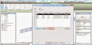
- Go to Baluster Placement and click Edit
- Under Baluster family, you should now be able to select the custom baluster we loaded into the project.

- Also change the posts to our custom baluster and Use "Distance from Previous" for Spacing click OK. We should have the balusters in place.


Use the tab key on the keyboard to select the Handrail then go to "Edit type" change the profile to the one we created then OK.

Any question. please feel free to comment or ask your question.
missing some steps on the revit baluster instructions, which work planes do you set to when making the center part? Do you have to lock the center to the reference plains, if so how? You cannot create the top and bottom parts using the reference plane as front/back and use the uploaded pic as a guide as it makes it impossible to draw in the left elevation view.
ReplyDeleteI am sorry that I am just replying to your comment. To answer your first question, you only need to lock the top and the bottom face of the center part to the top and the bottom square extrusions and constrain the curved part by adding radius dimension. But then again you must decide the extent of flexibility you want to add to the parameter of the railing ,bearing in mind that standard railing cannot be lower than 900mm. As for your second comment, your are right. the tracing must be done in the view where the ref.image is inserted.
DeleteThank for your comment
ReplyDeleteHi, Can you please share the process, how you made that Inclined glass railing as on the top of this blog.
ReplyDeleteHi, Can you please share the process, how you made that Inclined glass railing as on the top of this blog. That is what we want to see.
ReplyDeletethe safety of any residential or industrial assets. Very clean to put in. Austin fence supply atx decorative wrought iron. Welcome to atx fence deliver, austin, tx atx fence deliver is a producer and wholesaler of high-quality, powder covered decorative iron merchandise. Our neighborhood warehouse.fencing materials
ReplyDeleteYour blog is too much amazing. I have found with ease what I was looking. Moreover, the content quality is awesome. Thanks for the nudge! custom home design Horseshoe Bay tx
ReplyDeleteThanks for yout feedback
Delete